
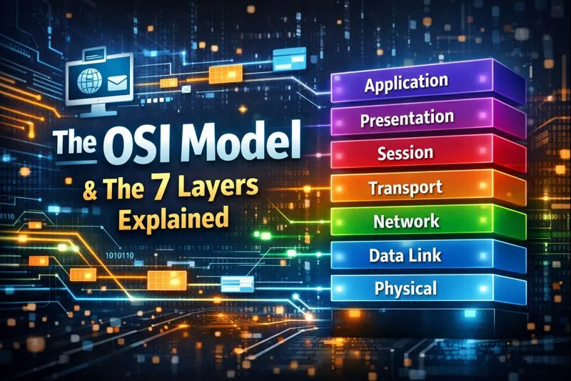
OSI Model: is a framework for understanding how networking systems communicate. It breaks down these communications into seven layers: Physical, Data Link, Network, Transport, Session, Presentation, and Application. It was developed in 1984 by the International Organization for Standardization (ISO) to promote interoperability between different products and software. While it may not perfectly match modern systems, it remains a valuable tool for describing network architecture.
Table of Contents
What Is the OSI Model?
The OSI model explains how computers communicate over networks using seven layers. It was the initial standard model for network communication, embraced by major computer and telecom companies in the early 1980s.
Even though the modern Internet relies on the TCP/IP model instead of OSI, the OSI 7-layer model is still popular. It aids in understanding network operations and diagnosing networking issues. OSI was developed by leading computer and telecom companies in 1983 and became an international standard endorsed by ISO in 1984.
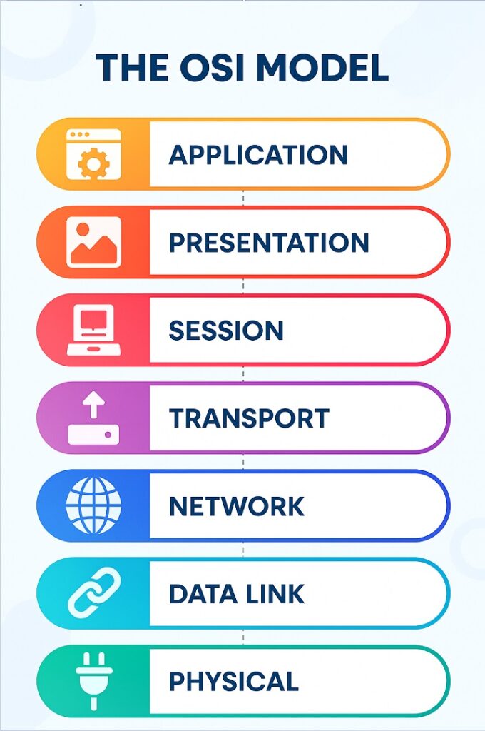
OSI Model Explained: The OSI 7 Layers
We’ll explain the OSI layers from top to bottom, starting with the layer closest to the end user, which is the physical layer, and moving down to the application layer, which deals with the actual hardware connections.
1. Physical Layer
The Physical Layer is the first layer in the OSI model. It deals with the actual physical connection between devices, such as cables, connectors, and signals. Its main job is to transmit raw data bits over a communication channel. Think of it as the foundation of network communication, handling the actual transfer of data signals through physical mediums like wires or radio waves.
The physical layer manages the actual cable or wireless connection between network nodes. It defines the connector, the type of cable or wireless technology used, and handles the transmission of raw data—just a series of 0s and 1s—while controlling the bit rate.
2. Data Link Layer
At the data link layer, connected nodes transfer data between each other using frames. This layer also fixes errors from the physical layer. Within the data link layer, there are two sub-layers. The first one, called media access control (MAC), manages how devices send data over a network, including flow control and multiplexing. The second sub-layer, logical link control (LLC), handles flow and error control over the physical medium and identifies line protocols.
The data link layer sets up and ends connections between physically linked nodes on a network. It divides packets into frames and sends them from one point to another. This layer has two components: Logical Link Control (LLC), which manages network protocols, checks for errors, and synchronizes frames, and Media Access Control (MAC), which uses MAC addresses to link devices and control data transmission permissions.
3. Network Layer
The network layer receives frames from the data link layer and sends them to their intended destinations using logical addresses like IP (internet protocol). Routers play a vital role at this layer, directing information between networks to ensure it reaches its destination.
The network layer does two key things. First, it divides segments into network packets and puts them back together when received. Second, it figures out the best route for packets to travel across a physical network. It relies on network addresses, usually IP addresses, to guide packets to their destination.
4. Transport Layer
The transport layer handles delivering data packets and checking for errors. It controls the size, sequence, and transfer of data between systems and hosts. A common example of the transport layer is TCP (Transmission Control Protocol).
The transport layer divides data from the session layer into “segments” during transmission and puts them back together on the receiving end. It manages flow control by adjusting data transmission speed to match the receiving device’s capability and checks for errors, requesting retransmission if needed.
5. Session Layer
The session layer oversees conversations between computers. It sets up, manages, and ends sessions or connections between machines. Services of the session layer also involve authentication and reconnections.
The session layer sets up communication channels, called sessions, between devices. It handles opening, maintaining, and closing these sessions during data transfer. Additionally, it can establish checkpoints so that if communication is interrupted, devices can resume from the last checkpoint.
6. Presentation Layer
The presentation layer formats or translates data for the application layer according to the syntax or semantics that the application uses. It’s sometimes referred to as the syntax layer. Additionally, this layer can manage encryption and decryption needed by the application layer.
The presentation layer readies data for the application layer. It specifies how devices should encode, encrypt, and compress data to ensure it’s received accurately on the other side. This layer takes data from the application layer and prepares it for transmission over the session layer.
7. Application Layer
At this layer, both end users and applications directly interact with software applications. It provides network services to end-user applications like web browsers or Office 365. The application layer manages communication partners, resource availability, and synchronization of communication.
The application layer is utilized by end-user software like web browsers and email clients. It furnishes protocols that enable software to transmit and receive information and present meaningful data to users. Examples of application layer protocols include HTTP, FTP, POP, SMTP, and DNS.
Advantages of OSI Model
The OSI model benefits users and network operators by:
- Assisting in determining the necessary hardware and software for network construction.
- Facilitating understanding and communication of the process involved in components communicating over a network.
- Aiding in troubleshooting by pinpointing the problematic network layer, enabling focused resolution efforts.
For network device manufacturers and software vendors, the OSI model helps by:
- Enabling the creation of devices and software capable of interoperating with products from any vendor, fostering open interoperability.
- Defining the network components their products should interface with.
- Communicating to users the specific network layers their product operates within, such as solely at the application layer or across the entire stack.
OSI vs. TCP/IP Model
TCP/IP, created by the US Department of Defense, predates the OSI model and is simpler, combining multiple OSI layers into fewer:
- Layers 5, 6, and 7 of OSI are merged into one Application Layer in TCP/IP.
- Layers 1 and 2 of OSI are merged into one Network Access Layer in TCP/IP, but TCP/IP doesn’t handle sequencing and acknowledgment, leaving it to the transport layer.
Other key differences include:
- TCP/IP is a functional model designed to solve specific communication issues, while OSI is a generic, protocol-independent model.
- Most applications in TCP/IP use all layers, while in OSI, simple applications may not use all seven layers. Only layers 1, 2, and 3 are essential for any data communication in OSI.